
Doppler radar provides high quality data of movements in the radar’s surrounding environment, including the movement’s direction and speed, even while the radar itself remains stationary. However, the resulting data is often difficult to decipher on it’s own. Using machine learning we can recognize patterns like hand gestures from the messy signals generated by the Doppler radar. With TinyML, developers can easily run radar gesture recognition models on embedded devices with Doppler radar sensors using minimal device resources.
In this blog post, we will show you how to collect signal data from the Infineon Sense2GoL-Pulse development kit’s on-board Doppler radar sensor (the BGT24LTR11 24 GHz transceiver IC), forward this data to your Edge Impulse project, train an inferencing model, and deploy the Arduino inference library back to your device.
What is radar data?
Before we start collecting data from our Infineon Sense2GoL development kit, we first need to understand what it is we are actually collecting.
On-board the Infineon Sense2GoL-Pulse are two key pieces of hardware required for processing and collecting Doppler radar signals, the BGT24LTR11 24 GHz transceiver IC and the XMC4700 32-bit ARM® Cortex™-M4 MCU.
Information gathered by the BGT24LTR11 radar chip is passed through a signal modulator to create signals which are then sent through the ADC inputs of the XM4700 MCU. The MCU samples the IF (intermediate frequency) signal channels on the radar chip and then communicates the collected data over Serial USB connection to your computer. This collected data contains two periodic quadrature signals that are the basis of radar signal processing, also known as IQ signals. Where “I” is the reference “in-phase” signal, and “Q” is the “quadrature” signal which is shifted by 90 degrees out-of-phase. Essentially, the I signal contains a cosine wave and the Q signal contains a sine wave of the collected data, which can then be analyzed in the time/frequency domain on or off board.
For more information on radar signals, check out “What’s Your IQ - About Quadrature Signals...”.
How to get started
- Purchase an Infineon Sense2GoL-Pulse development kit.
- Sign up for an Edge Impulse account.
- Create a new Edge Impulse project.
- Install the Edge Impulse CLI - we’ll use this to send data from your development board to Edge Impulse.
- Install Segger J-Link - to connect to the Infineon Sense2GoL board over serial connection.
- Install the Arduino IDE - and install the Infineon XMC board package:
- Select ‘Preferences’ > ’Additional Boards Manager URLs’, add the following URL https://github.com/Infineon/Assets/releases/download/current/package_infineon_index.json
- From the Boards manager: ’Tools > Board > Boards Manager...’, search for and install ‘Infineon’s XMC Microcontroller’
- Update the Infineon Arduino hardware folder with the latest code from the 24Ghz-radar branch on GitHub: https://github.com/Infineon/XMC-for-Arduino/tree/24Ghz-radar
- Install the Arduino CLI.
Forwarding radar data to your Edge Impulse project
Connect your Sense2GoL-Pulse development kit to the computer via the DEBUG USB port.
We use the following code to capture radar readings and print them to the serial output. You can find more details on the protocol in the Data Forwarder guide.
Create a new folder on your computer called “Sense2GoL-Pulse-serial” and create a new file inside this folder called “Sense2GoL-Pulse-serial.ino”. Copy and paste the following code into this .ino file:
#include <IFXRadarPulsedDoppler.h>
#include <LED.h>
IFXRadarPulsedDoppler radarDev;
#define FRAME_SAMPLES 256
float raw_i[FRAME_SAMPLES];
float raw_q[FRAME_SAMPLES];
void myRawDataCallback(raw_data_context_t context)
{
  uint32_t frameCnt   = radarDev.getRawDataFrameCount(context);
  uint16_t numSamples = radarDev.getNumRawDataSamples(context);
  radarDev.getRawData(context, raw_i, raw_q, FRAME_SAMPLES);
  // use only one sample out of 32, so just one per frame
  Serial.print(raw_i[5]);
  Serial.print("\t");
  Serial.println(raw_q[5]);
}
void setup() {
  Serial.begin(500000);
  radarDev.registerRawDataCallback(myRawDataCallback);  // register a handler to receive raw data
  radarDev.enableAlgoProcessing(false); // set to false to disables the lib internal radar algo processing
  // start the radarDevice, to read the default parameter
  radarDev.initHW();
  radarDev.begin();
 // Frame rate of 75Hz
 radarDev.setNumSamples(32);   // 32 Samples
 radarDev.setSampleFreq(3000);
 radarDev.setSkipSamples(8);   // add 8 skip samples, to "burn" 4 msec before, so 40 Samples at 3kHz gives 75Hz
Paste this code into your “Sense2GoL-Pulse-serial.ino” Arduino sketch, then run the following commands with the Arduino CLI to compile and flash the program onto your board, for example:
C:\Sense2GoL-Pulse-serial> arduino-cli compile --fqbn Infineon:arm:XMC4700_Radar_Baseboard Sense2GoL-Pulse-serial -e --output-dir .
C:\Sense2GoL-Pulse-serial> arduino-cli upload --fqbn Infineon:arm:XMC4700_Radar_Baseboard --input-file .\Sense2GoL-Pulse-serial.ino.hex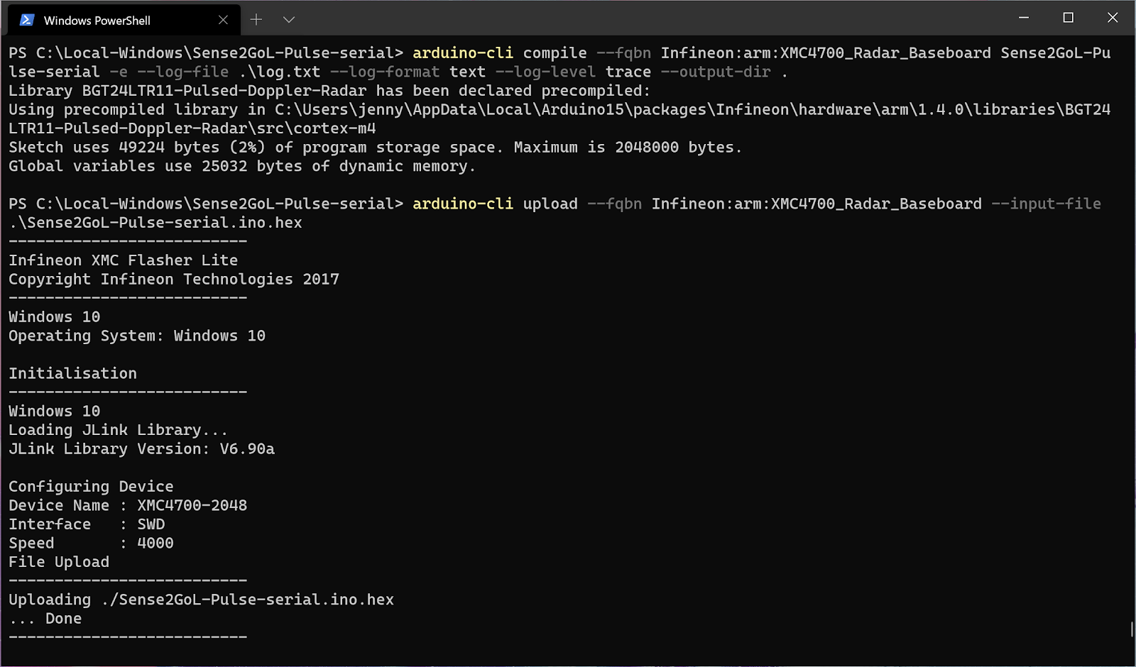
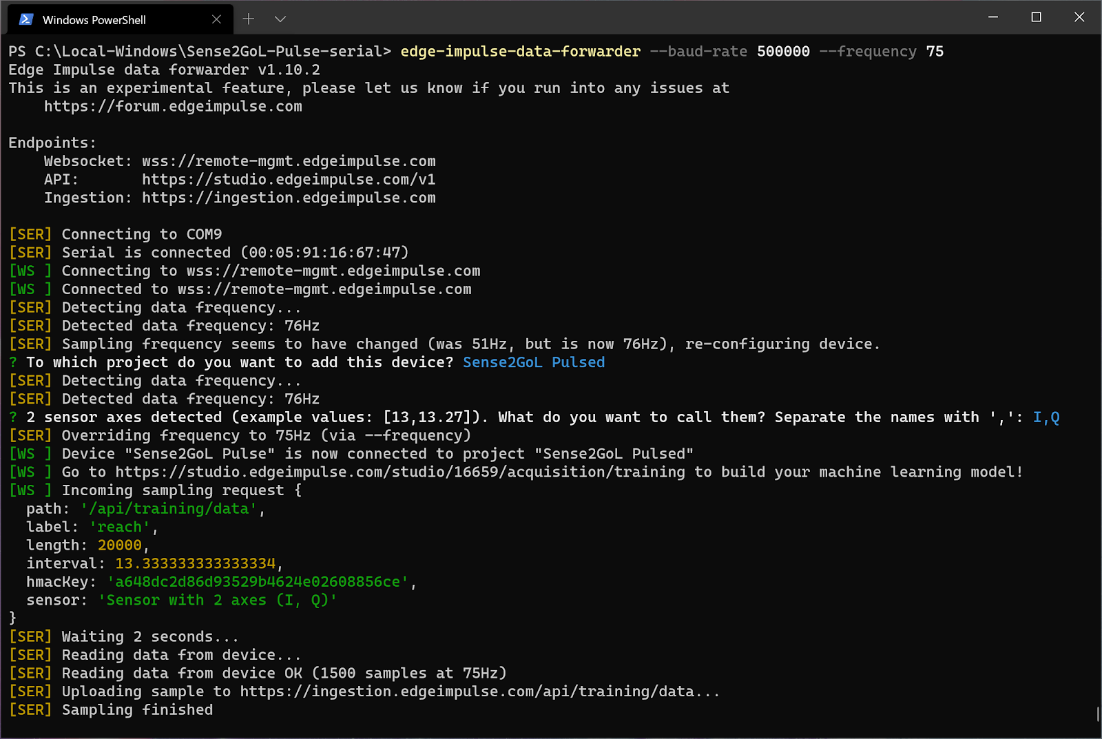
Run edge-impulse-data-forwarder --baud-rate 500000 --frequency 75 to start forwarding the radar data from your computer’s serial terminal to your Edge Impulse Project. Select your Edge Impulse project, configure your sensor’s information, and override the sampling frequency:
Finally head to your Edge Impulse project, and click Data acquisition. Your Infineon board is now visible under ‘Record new data’:
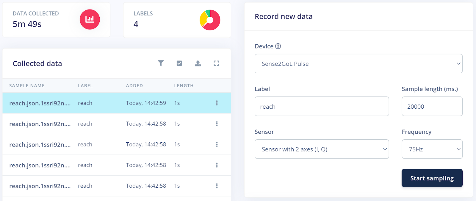
Now you can start collecting data. Using the Start sampling button and Label input field, capture ~3 minutes of data per gesture from the radar, where each sample is approximately 1 second long (I created 1200 ms length samples). Make sure to change the Label for each gesture you are sampling!
I have collected ~14 minutes of training data and ~3 minutes of testing data for 4 different types of gestures: nothing (ambient environment/no motion), pinch, tap, and reach:
Using Edge Impulse data acquisition tools
Collecting this much high quality labeled data is tedious, thankfully Edge Impulse has tools built into the Data acquisition tab to make things easier for us.
For example, if I want to continuously perform a gesture for 20 seconds rather than record 20 individual 1 second samples, Edge Impulse can let me splice up that 20 second sample into a bunch of smaller discrete samples (one gesture per 1 second sample, for this blog post I am using 1200 ms samples).
Set the Sample length (ms.) to 20000, the Label to the gesture you are performing, then click Start sampling and continuously gesture with your hand above the radar. Then in Edge Impulse, select the 20 second sample’s option button and click Split sample:
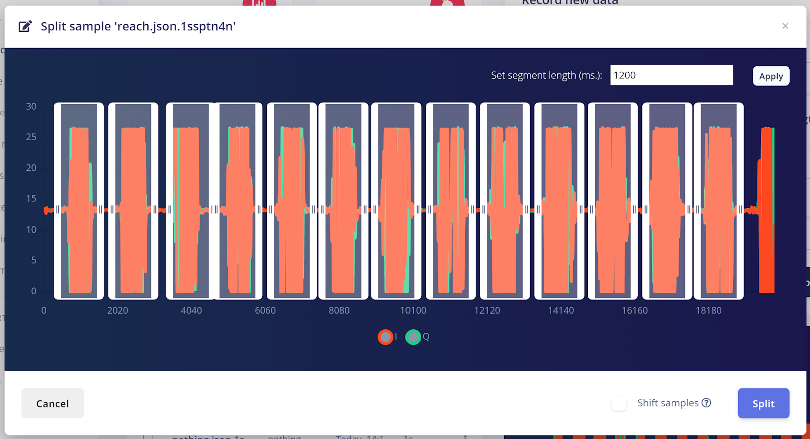
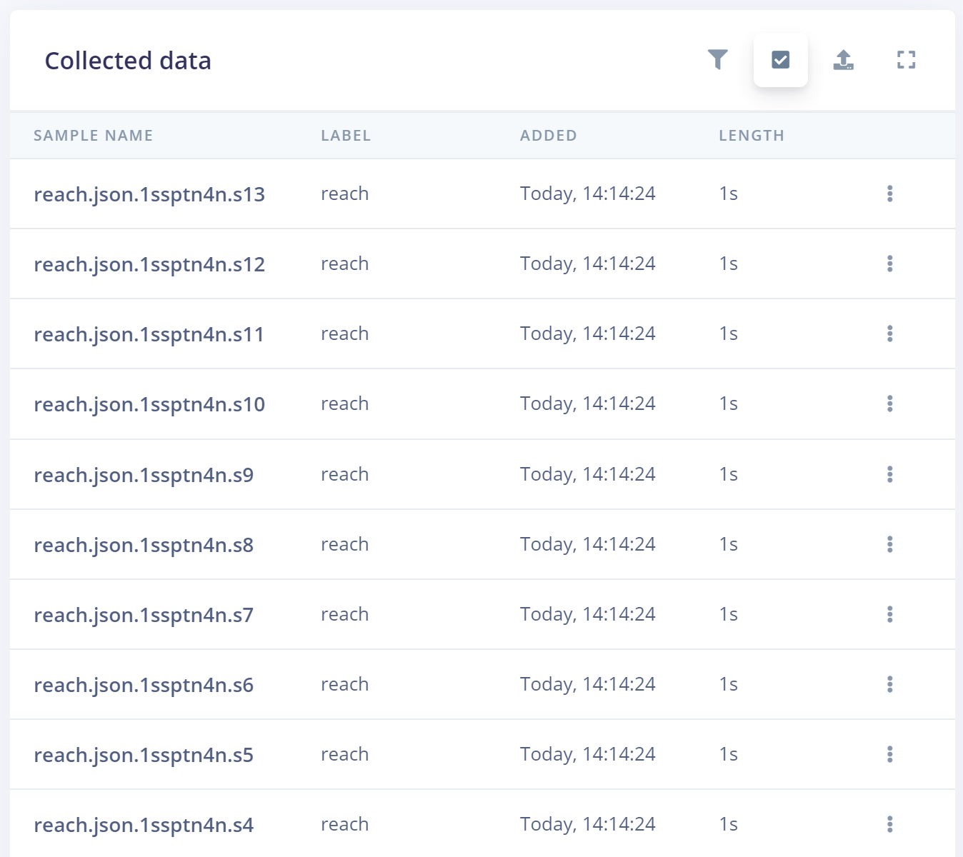
Move the generated sample segments to align with 1 gesture per 1s sample, and then click Split. We now have 10-15 individual samples rather than one long 20 second sample, these split samples have names ending in *.s1, *.s2, etc.:
Building and training your model
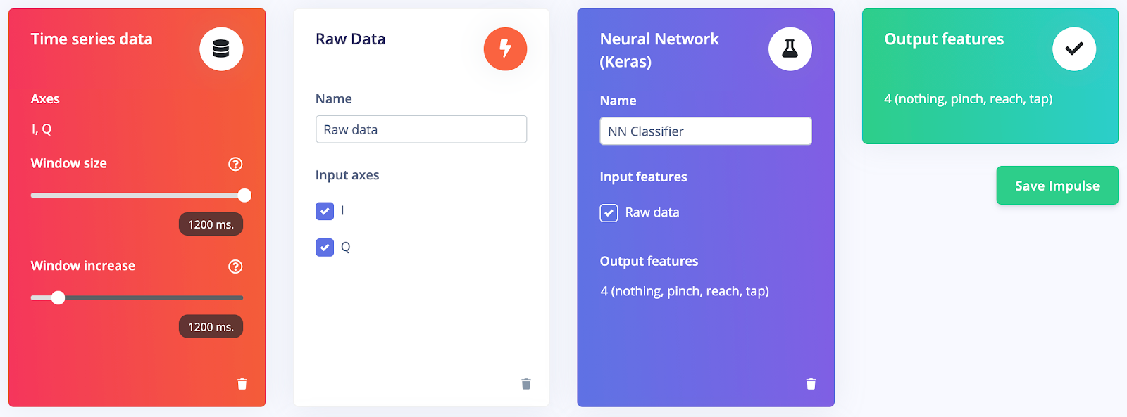
Now that we have collected training and testing data, we can begin building and training our gesture recognition model. In your Edge Impulse project, click on the ‘Impulse design’ tab. Set the window size and window increase to the full length of your data samples. Because the data we have collected has already been passed through a signal modulator, click Add a processing block and select the ‘Raw Data’ block. Next, click Add a learning block and select the ‘Neural Network (Keras)’ block. Your impulse design should look like this:
Next, click the Raw data tab on the left, select Save parameters as we have nothing to configure on this page, and Generate features from the IQ signals.
Onto the machine learning model, click the NN Classifier tab and change the Neural Network settings to the following, you can change the neural network architecture layers by clicking Add an extra layer:
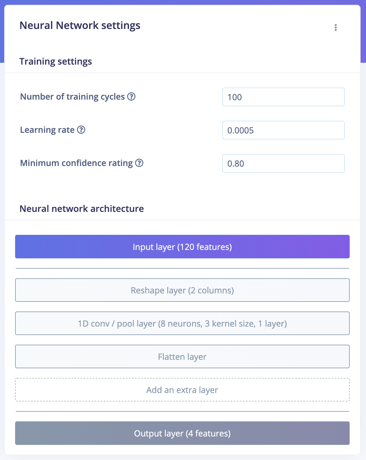
Instead of using the default Dense layers, we have chosen to Reshape the data into two dimensions based on the raw data signals (I and Q), perform a 1D convolution on their features and finally flatten the resulting two dimensional data back into one dimension. Dense layer does not work as well for this data input because we are not doing any other pre-processing on the signals before training our model with it.
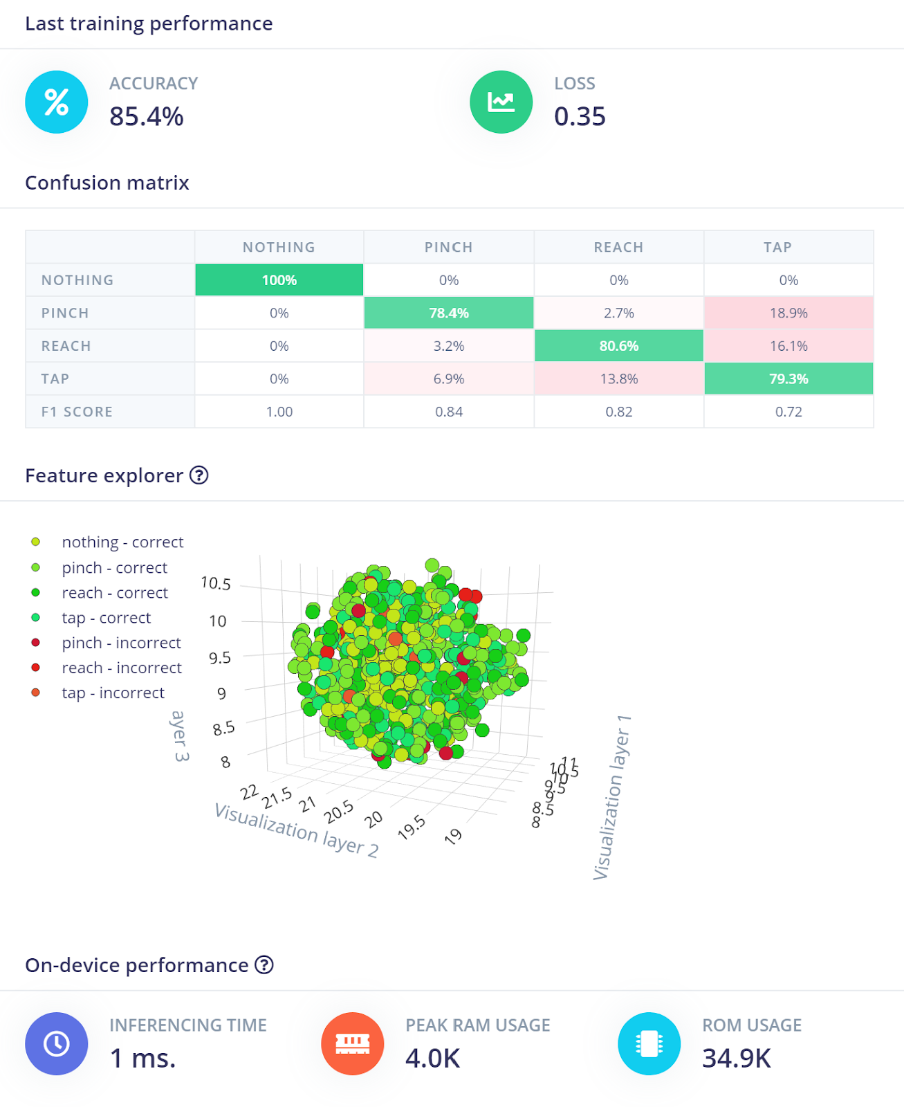
Now select Start training, you should see a model accuracy of about 85-95%. You can also view which data samples are causing your model trouble under the “Feature explorer” section below the “Confusion matrix.” With the data I collected, I was able to achieve an accuracy of 85.4%:
Running inferencing on your board
With the model trained, we can now deploy the model back to your development board and recognize gestures directly on the device.
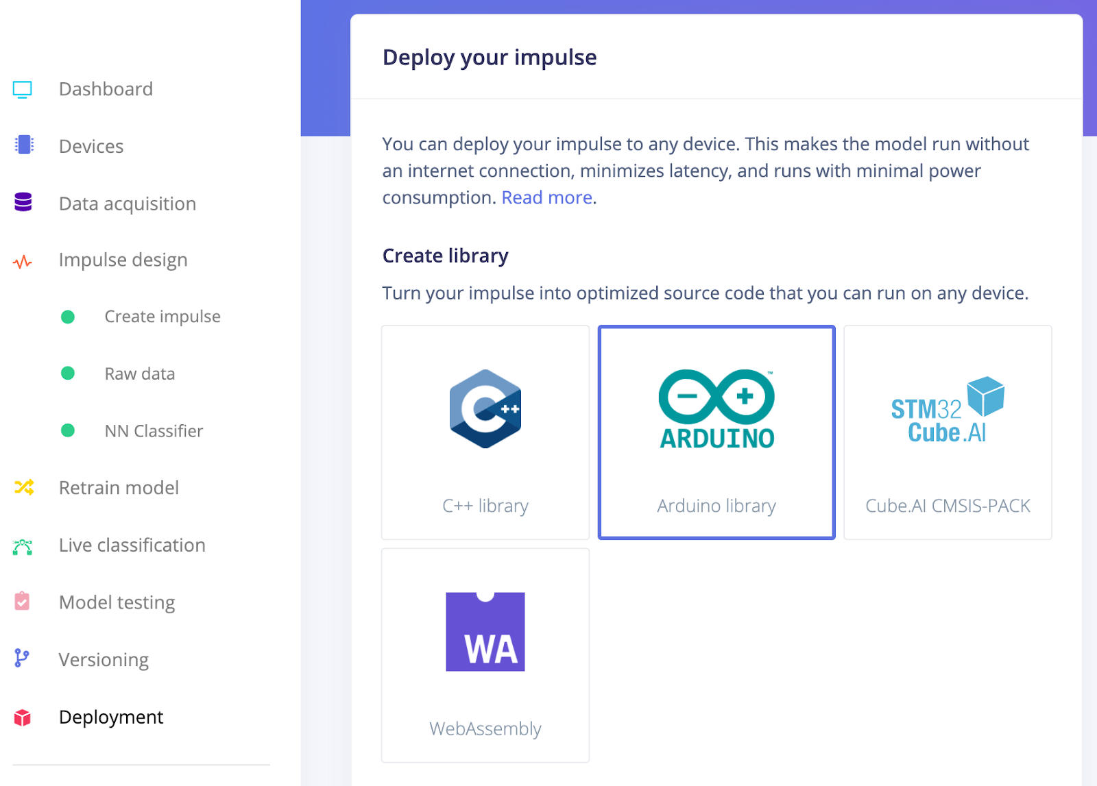
Select and Build the Arduino library from the Deployment tab:
Now, follow the Running your impulse locally - Arduino guide to import your .zip inferencing library into the Arduino IDE.
Create a new sketch (make a new folder called “Radar-inferencing” and create a sketch file inside called “Radar-inferencing.ino”) and copy and paste the code below to collect radar data, and inference in real time on the device:
#include <sense2gol-pulse_radar_inference.h>
#include <IFXRadarPulsedDoppler.h>
#include <stdarg.h>
IFXRadarPulsedDoppler radarDev;
// Allocate a buffer here for the values we’ll read from the radar
float buffer[EI_CLASSIFIER_DSP_INPUT_FRAME_SIZE] = { 0 };
#define FRAME_SAMPLES (EI_CLASSIFIER_DSP_INPUT_FRAME_SIZE / 2)
float raw_i[FRAME_SAMPLES];
float raw_q[FRAME_SAMPLES];
void myRawDataCallback(raw_data_context_t context)
{
 uint32_t frameCnt   = radarDev.getRawDataFrameCount(context);
 uint16_t numSamples = radarDev.getNumRawDataSamples(context);
 radarDev.getRawData(context, raw_i, raw_q, FRAME_SAMPLES);
 size_t i = 0;
 size_t k = 0;
 for(i = 0, k = 0; i < EI_CLASSIFIER_DSP_INPUT_FRAME_SIZE; i++, k += 2) {
   buffer[k] = raw_i[i];
   buffer[k + 1] = raw_q[i];
 }
}
void setup()
{
 Serial.begin(500000);
 Serial.println("Edge Impulse Infineon Radar Gesture Inferencing Demo");
 radarDev.registerRawDataCallback(myRawDataCallback);  // register a handler to receive raw data
 radarDev.enableAlgoProcessing(false); // set to false to disable the lib internal radar algo processing
 // start the radarDevice, to read the default parameter
 radarDev.initHW();
 radarDev.begin();
 // Frame rate of 75Hz
 radarDev.setNumSamples(32);   // 32 Samples
 radarDev.setSampleFreq(3000);
 radarDev.setSkipSamples(8);   // add 8 skip samples, to "burn" 4 msec before, so 40 Samples at 3kHz gives 75Hz
Now run the following commands with the Arduino CLI to compile and flash the program onto your board, for example:
C:\Radar-inferencing> arduino-cli compile --fqbn Infineon:arm:XMC4700_Radar_Baseboard Radar-inferencing -e --output-dir .
C:\Radar-inferencing> arduino-cli upload --fqbn Infineon:arm:XMC4700_Radar_Baseboard --input-file .\Radar-inferencing.ino.hex
Next steps
There’s some ways we can also increase our model’s accuracy:
- Collect more data of the same gestures
- Collect more data of the same gestures with varying speeds and direction
- Increase/decrease the number of classes (the gestures)
We can also change the Arduino inferencing example to inference based on a continuous data stream from the radar, see how you can accomplish this by following the Continuous audio sampling tutorial.
You can also view and clone the public Edge Impulse project used in this blog post here: https://studio.edgeimpulse.com/public/16659/latest
Real life applications
How is machine learning with Doppler radar useful in real life or in industrial applications?
- Light switch control
- Home automation (sans Alexa, Google Home, etc.)
- Predictive maintenance (identifying when packages fall off of an assembly line, etc.)
- & more!
---
Jenny Plunkett, User Success Engineer at Edge Impulse